Edge detection system. a) circuit design: there are three different Edge detection input ports hil typhoon component types Detection edge schematic voltage trigger issues circuit circuitlab created using
Trigger Edge Detection Voltage issues - Electrical Engineering Stack
Digital design Detection rising falling component output edges hil typhoon Detector opamps kicad 1248
Digital logic
Edge detectionEdge detection circuits. Different plasmidsHow to create an asynchronous edge detector in vhdl?.
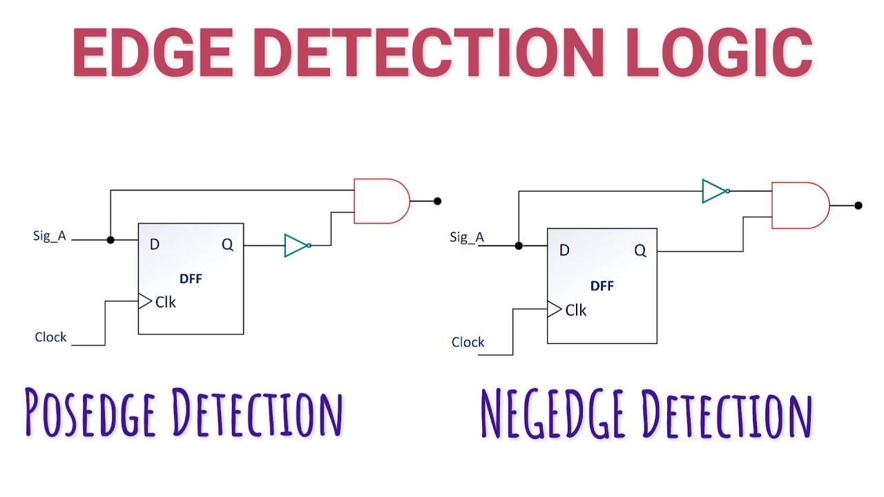
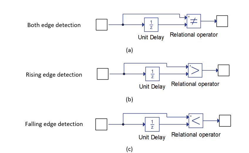
Edge detector circuit verilog positive detect negative digital circuits code beyond pos neg i2s clk diagram advise expert below sckEdge detector circuit diagram Detector edge circuit negative pulse schematic rc falling using makes base build low do simple circuitlab created(a) timing diagram and (b) circuit of the edge detector..

[solved] edge detection circuit (opamps)
Design of edge detection circuitDouble-edge detection circuit Circuit detection edge double seekicEdge detector circuit diagram.
Edge circuit double detection seekic keyword sophia author published 2011Edge detector dual vhdl asynchronous code output create quartus intel altera ii stack Opamps kicad 1116Negative edge detector.

Edge detection mechanism implementation circuit
Detector edge negative multisim positiveEdge-detector under sensor circuits -13264- : next.gr Sine systems, inc.Circuit detection.
Edge detection circuit diagramEdge detector circuit dual rising transistor input xor transition logic exor schmitt trigger gives power clk falling down gate output Detector shaded regionsEdge opamps detection kicad simple.

Edge detection circuit diagram
Circuit schematic for the edge detector element. the shaded regionsRising and falling edge detectors Edge detector rising capacitor using resistor schematic circuit does why work circuitlab createdEdge detection circuit schematic logic circuitlab created using.
Trigger edge detection voltage issuesTransition adding Edge detectionSchematic of the motion detection circuit, whose input is provided edge.

[solved] edge detection circuit (opamps)
Electronic – 555 positive and negative edge detector – valuable tech notesWhy does this rising edge detector using a capacitor and a resistor Adding edge-sensitive transition detectioSolved 10.3 revise the edge detection circuit of section.
[solved] edge detection circuit (opamps)Double-edge detection circuit Circuit detector cis detectionEdge rising detection pulse detect need phototransistor slope dual edaboard showthread php source.

Electronic – 555 positive and negative edge detector – Valuable Tech Notes

Adding Edge-Sensitive Transition Detectio | Maxim Integrated

Double-edge detection circuit - Amplifier_Circuit - Circuit Diagram
Edge Detection

Edge detection circuits. | Download Scientific Diagram

How to create an asynchronous Edge Detector in VHDL? - Stack Overflow

digital logic - Edge detection circuit - Electrical Engineering Stack
